Nudged Elastic Band (NEB)#
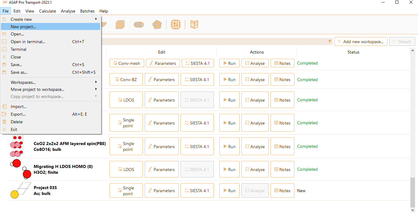
Or by editing the project type of a previously existing project.

A widget will be opened to choose the type of project. Select Nudged Elastic Band from the list of possible project types implemented in ASAP.

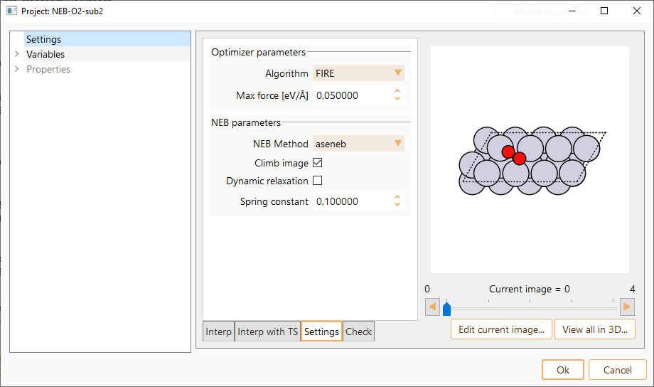
Then click on the Parameters icon to open the NEB parameters widget.

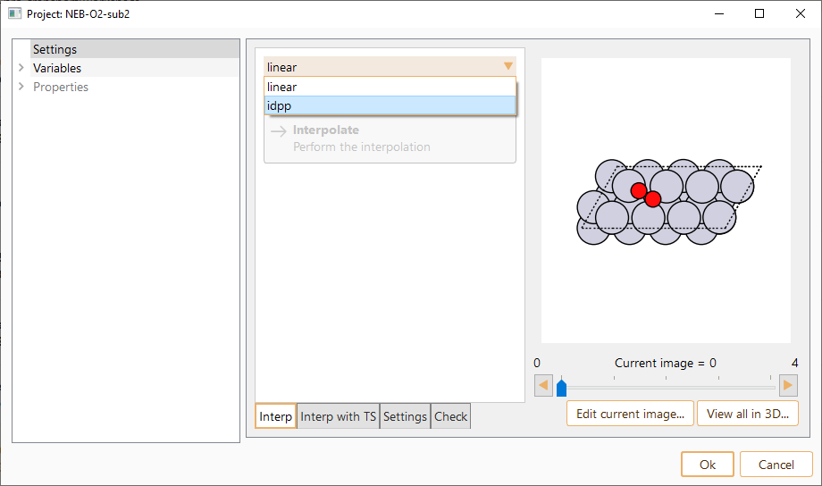
linear. It is the most simple approach. It is used for linear interpolation of the atomic coordinates.
Image dependent pair potential interpolation (idpp). A method that has been developed to provide an improvement to the initial guess for the NEB path. S. Smidstrup, A. Pedersen, K. Stokbro and H. Jonsson, Improved initial guess for minimum energy path calculations, J. Chem. Phys. 140, 214106 (2014).

Algorithm. Select one of the possible algorithms to perform the optimisation.
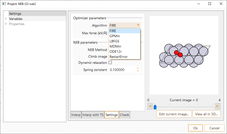
Max force. The force on all individual atoms for the convergence criterion. In units of eV/Angström.
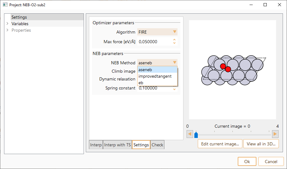
aseneb: Standard NEB implementation.
improvedtangent: A modification of the NEB for finding minimum energy paths. One of the images is made to climb up along the elastic band to converge rigorously on the highest saddle point. Also, variable spring constants are used to increase the density of images near the top of the energy barrier to get an improved estimate of the reaction coordinate near the saddle point. Method reported by G. Henkelman and H. Jonsson, Chem. Phys, 113, 9978 (2000). https://doi.org/10.1063/1.1323224
eb: Full spring force implementation. The method reported by E. L. Kolsbjerg, M. N. Groves, and B. Hammer, J. Chem. Phys, 145, 094107 (2016) https://doi.org/10.1063/1.4961868.
Besides, you can also select the following options:
Climb image. The climbing image is a small modification to the NEB method. This variation involves designating a specific image to behave differently to the rest of the chain. The selected image does not feel spring forces, and the component of the potential force parallel to the chain is reversed, such that it moves towards the saddle point. In general, the climbing image is not turned on until some iterations have been run without it (generally 20 \(\%\) to 50\(\%\) of the total number of iterations). It allows the adjacent images to provide a reasonably good approximation of the correct tangent at the location of the climbing image. The required number of iterations before the climbing image is not turned on depends on the adjacent images providing a reasonably good approximation of the correct tangent at the location of the climbing image.
Dynamic relaxation. The convergence of images is often non-uniform, and a significant fraction of computational resources can be spent calculating images that are below the convergence criterion. With a dynamic optimisation method, the convergence of each image is carefully monitored. An image is only optimised if the norm of the forces acting on the image is above the convergence criterion. The list of the maximum forces on the images is updated every force call; if a previously converged image goes out of tolerance (due to spring adjustments between the image and its neighbours), it will be optimised again. Dynamic optimisation is only efficient working in series.
Spring constant. Parameter controlling the spring forces added along the band between images to perform the constrained optimisation when running a NEB.
Click on the Check images… button to check and repair the images along the reaction path.

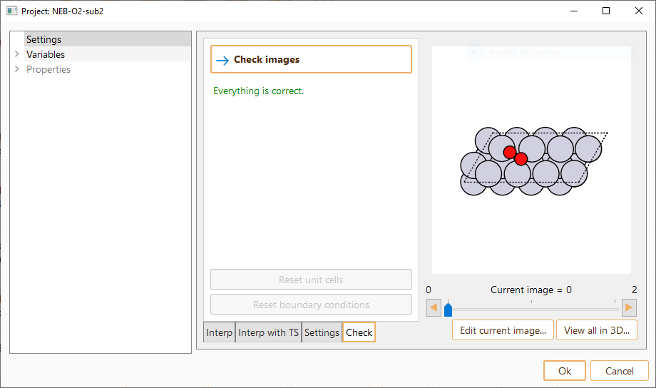
In some cases, it may be necessary to repair the images by using the following options:
Reset unit cells Press to set all unit cells equal to the unit cell of the first image.
Reset boundary conditions Press to set the boundary conditions of all the images to the boundary conditions of the first image.
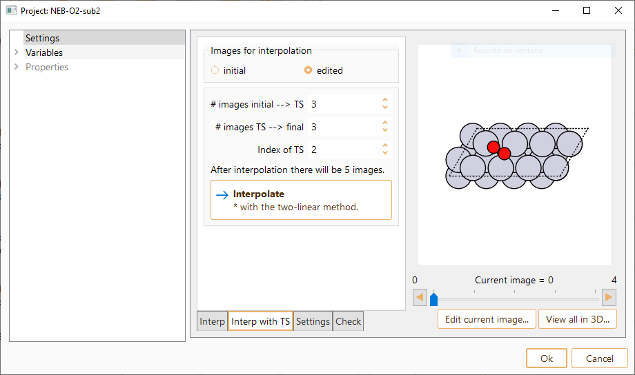
Press the button Edit current image… to edit any of the interpolated NEB images.

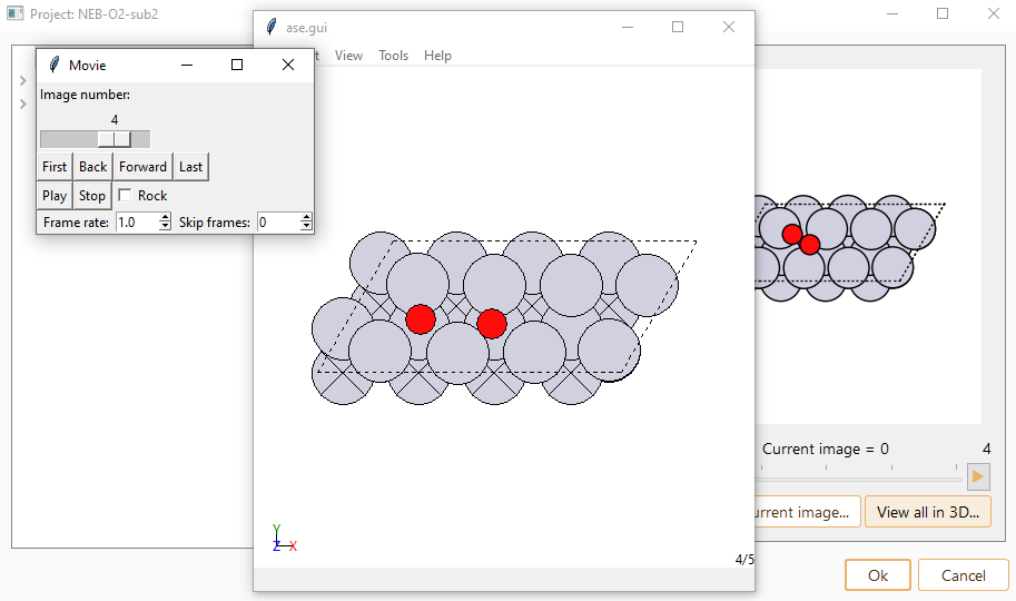
Press the button View all in 3D… to visualise NEB images in three dimensions.


Select Run button to run the NEB simulation.

We refer the user to Section Advanced Configuration and Remote Execution for further information on the Run widget.
NEB workflow: Analysis#


The left panel of the analysis widget contains information of all NEB converged images. Select View current in 3D…, to view the current image in three dimensions.
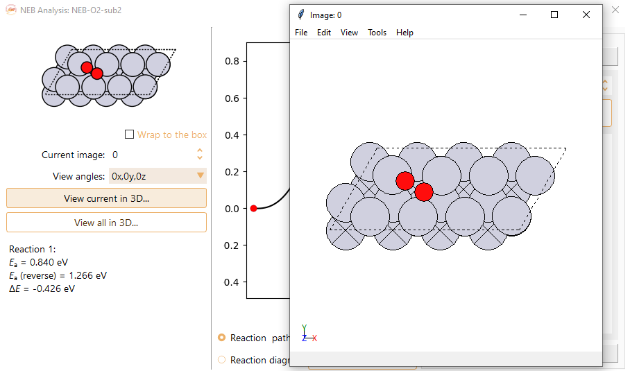
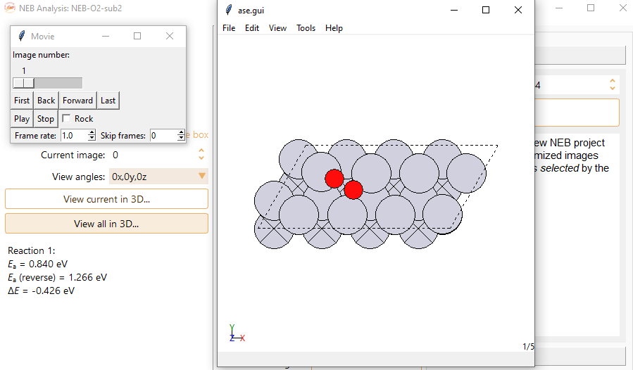
Select View all in 3D… to visualise all NEB converged images in three dimensions.
The dropdown menu View angles: allows you to rotate the system by 90 degrees around cartesian axes.


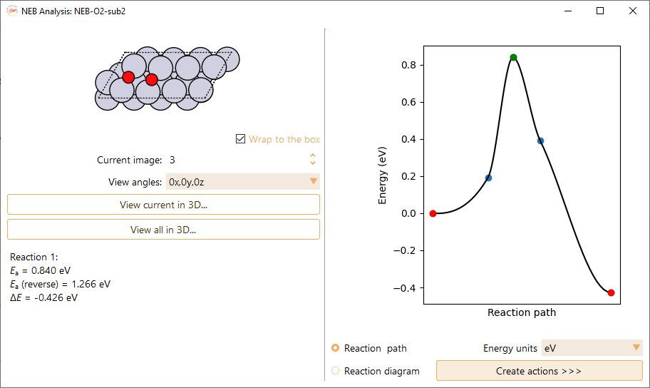
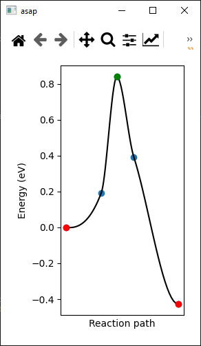
You can find the following information displayed at the bottom of the left panel,
E\(_a\): Activation energy of the forward barrier. The energy barrier is estimated based on the interpolated fit to the images.
E\(_a\)(reverse): Raw energy of the transition state.
\(\Delta\)E: Reaction energy.
The energy comes in units of eV, meV, kcal/mol, kJ/mol, Ry and Ha.

Press the Generate NEB button to create a new NEB project using selected images as initial and final states. This new project will appear at the bottom of the project tray.

Press the Generate Vibrations button to create a new Vibrations project for the computed transition state (image with maximum energy). This new project will appear at the bottom of the project tray.
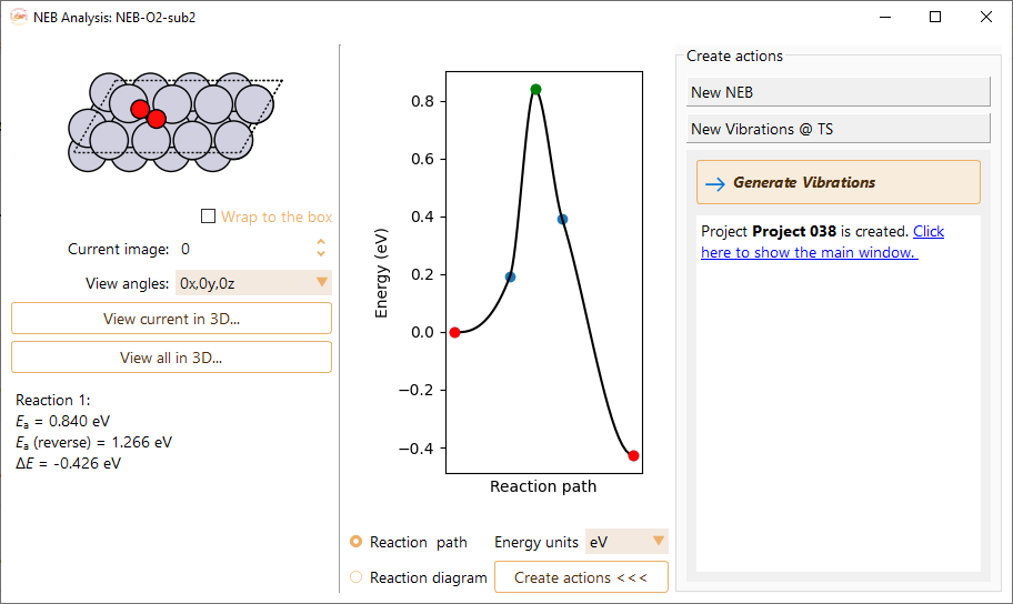
Click the Create actions < < < button to hide the right-hand side of the widget.
Use right-click on top of the figure to:

Save figure as…. The supported formats are pdf, png, jpg, jpeg, ps, eps, and svg.
Open in Matplotlib…. Matplolib library allows the user an interactive visualisation of the NEB figure (scale axis, zoom on specific X and Y values…).
Save a Matplotlib script as…. Save the Matplotlib script used to plot the figure.