The atomic structure builder#
Structure Modeling in ASAP#
Opening a new project#
XYZ (usually including atom numbers, element symbols and X, Y, and Z coordinates).
CIF (standard text file format for representing crystallographic information).
STRUCT_OUT (SIESTA output file with cell vectors in Angstrom and atomic positions in fractional coordinates).

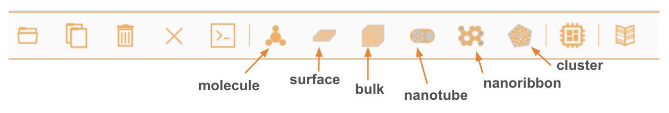
Structure builder/viewer interface#
Molecules#

Bulk#
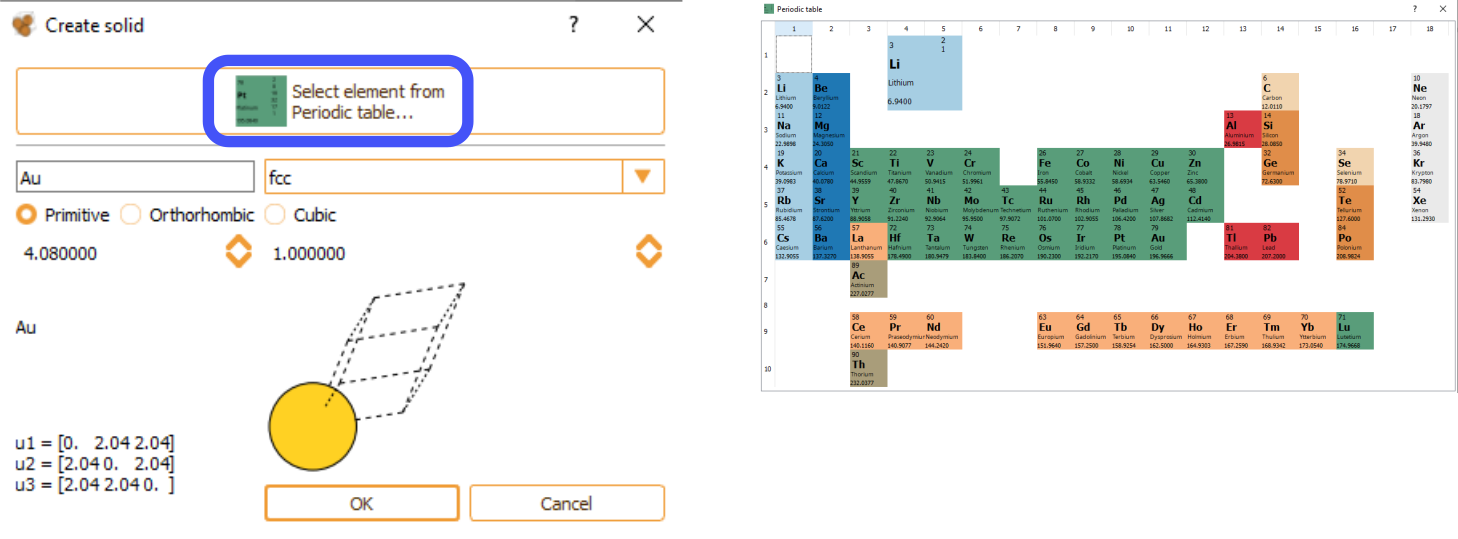
As an alternative, you can manually type the element name and its crystal structure. In this case, the specification of correct lattice constants is user responsibility. The bulk widget automatically shows the cell vectors associated with the indicated lattice parameters. Available options include the possibility for the user to select among, primitive, orthorhombic and cubic cell structure and the cell parameter.
Surface#
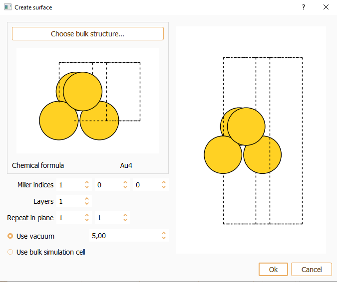
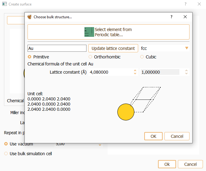
Press the Choose bulk structure… button to build the surface from the bulk structure (using the bulk widget described above).

Miller index. Miller indices determine the orientation of a surface. The parallel crystallographic plane is defined by the integer numbers (hkl). You can specify the desired Miller index along the three axes of the simulation cell. The smallest periodic structure fulfilling this specification is created.
Layers. You can indicate the number of equivalent layers of the slab.
Repeat in plane. To indicate the number of repetitions of the unit cell in x and y directions.
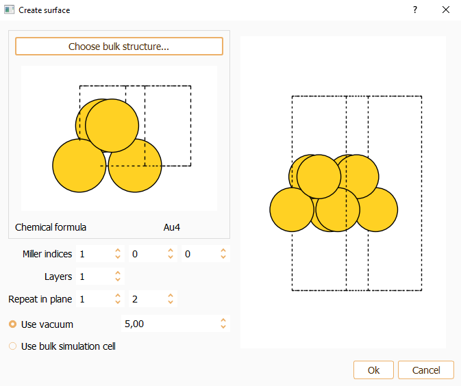
Press the OK button to close the surface widget after the parameters are properly set.

Alternatively, you have the option to extract a surface from a bulk. Begin by importing the bulk into ASAP, for instance using a CIF file. Click File in the menu bar and then select the Import option:
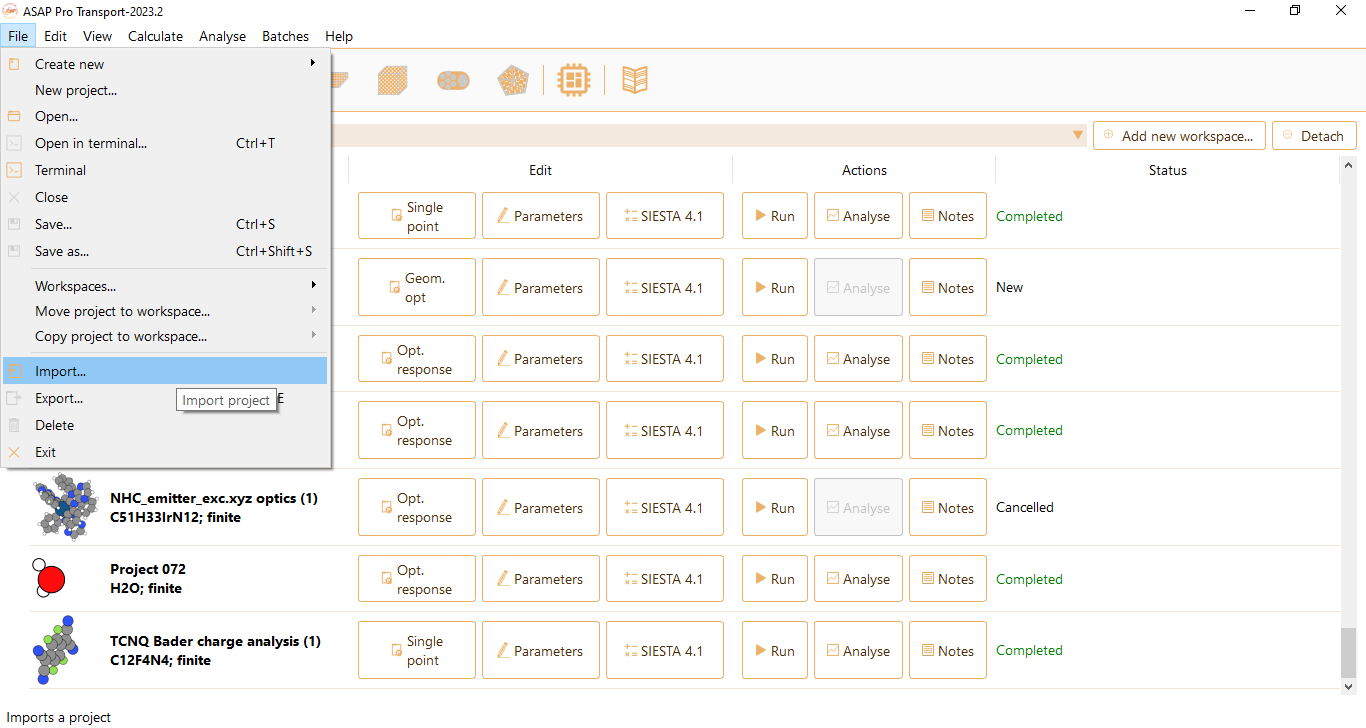
To cut a surface from the imported bulk, select the corresponding project, then click File in the menu bar, select the option Create new and click Surface.

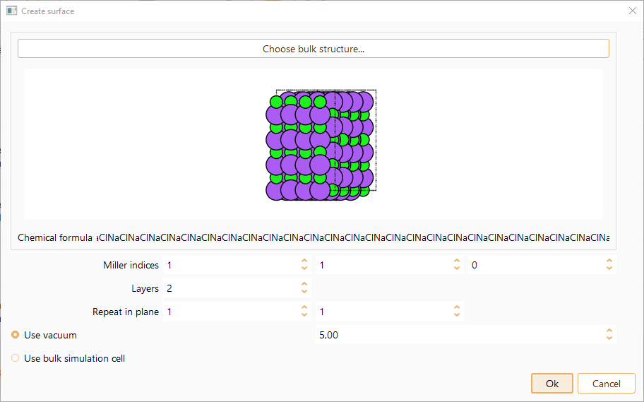
Click the OK button to close the surface widget. A new project will be created.
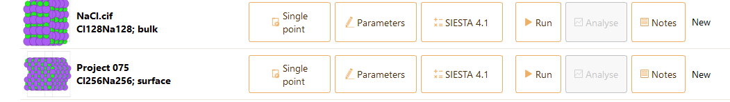
You can visualise the structure using a 3D viewer by double-clicking on the icon of the new project.

Nanotube#
You can use this widget to create a single-walled nanotube.

You can tune the following parameters:
Chemical symbol: chemical element to construct the nanotube from: C or Si
Chiral indices: the two components of the wrapping vector (n,m) that define the diameter and chiral angle of a nanotube.
Linear extent: number of unit cells.
Vacuum length: vacuum added in the non-periodic direction (z).
Bond length: bond length between neighbouring atoms.
Nanoribbon#
Use this widget to generate a nanoribbon within the x-z plane, positioning the nanoribbon along the z axis.
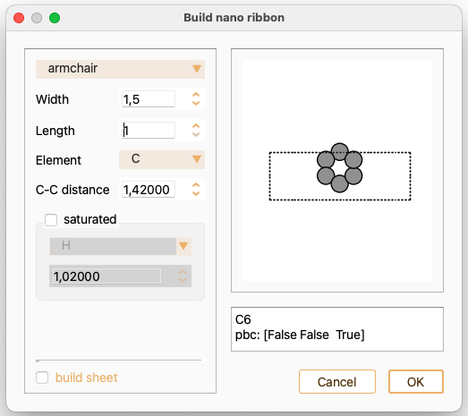
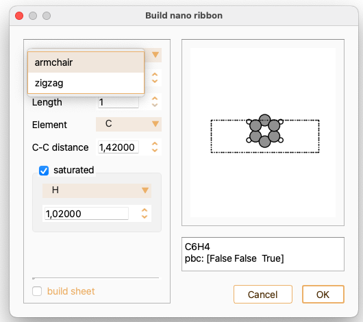
Begin by selecting the orientation of the ribbon, which must be either armchair or zigzag.
Adjust the following parameters using the widget:
Width: the width of the nanoribbon. For armchair nanoribbons, this may be half-integer to repeat by half a cell.
Length: the length of the nanoribbon.
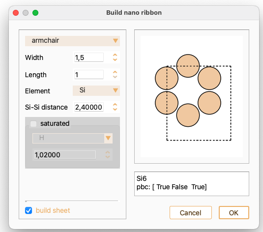
Element: chemical element to construct the nanoribbon from: C or Si
Bond length: bond length between neighbouring atoms.
Check the tick-box saturated if you want to position hydrogen atoms along the edge. Notice that alternative elements are available for edge saturation.

For zigzag nanoribbons, check the tick-box magnetic moment if you want to assign a magnetic moment to the atoms at the edges. You can input the magnetic moment value.

You can also build a sheet using this widget. In this case, the option to saturate the edge atoms is unavailable.
Nanoparticle#
You can use this widget to create an icosahedral nanoparticle (cluster) by specifying the number of layers in z direction.
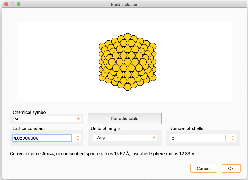
You can tune the following parameters:
Chemical symbol: The chemical element to construct the nanoparticle. Select an element from the periodic table (single click on the desired element) or the provided list. The lattice constant is automatically updated to the reference value for the selected element.
Lattice constant: The Lattice constant is set automatically if not specified such that the cell size will include the system without intercell interactions, plus 10% . In units of Angström, Bohr or nm.
Number of shells: Number of layers in one direction.
Visualisation#
Select one project in the project tray, go to View and select 3D viewer… for a high quality visualisation of the structure.

Ball-and-stick
Stick
Sphere

ASE GUI in ASAP#
ASAP is using a number of features implemented in ASE GUI. Those features are described in this section.
Visualisation#
Visualising a system with ASE GUI is straightforward with a mouse. Double-click on the structure icon you want to visualise,

Once ASE GUI is opened, you can use
the left mouse button to selects atoms
the right mouse button to rotate atoms
the middle button to translate the system on the screen
Measuring geometric quantities#
Depending on the number of selected atoms, ASE GUI automatically measures different quantities:
Single atom: xyz position and atomic symbol left mouse button to selects atoms
Two atoms: interatomic distance and symbols
Three atoms: all three internal angles and symbols
Four atoms, selected sequentially: the dihedral angle, e.g. the angle between bonds 12 and 34
More than four atoms: chemical composition of selection
Structure Manipulation#
Edit
The possible options are:
Select all
Invert selection
Select constrained atoms. Constrains may be modified in Tools/settings
Select immobile atoms
Hide selected atoms
Show selected atoms
Modify. To allow modification of the atomic symbol, an attached tag, or its magnetic moment
Add atoms. To add single atoms to an existing structure
Delete selected atoms
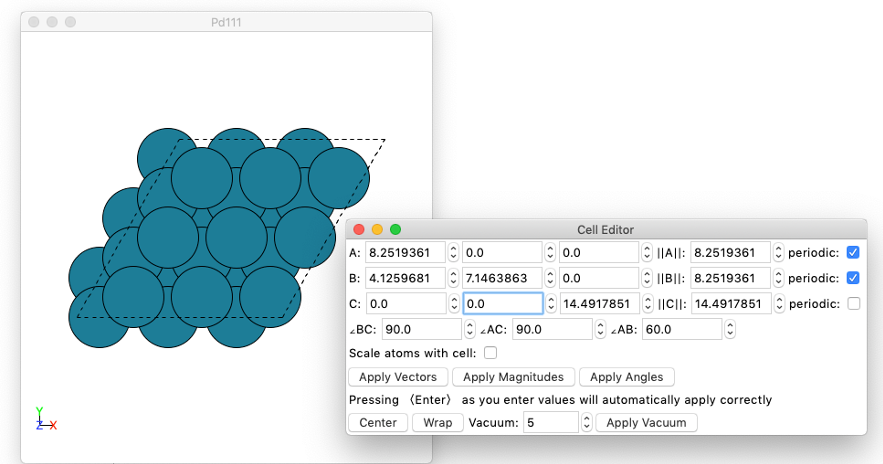
Edit cell. To edit cell vectors, and cell periodicity.
View
Show unit cell
Show axes
Show bonds
Show velocities. Currently disabled
Show forces. Option only available after completion of geometry optimisation project
Show Labels. The options are: atom index, magnetic moments, element symbol and initial charges
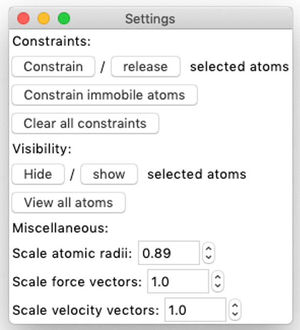
Settings. Basic view settings
Constraints.
Visibility. To mark selected atoms as invisible
Miscellaneous: scale atomic radii, force vectors and velocity vectors
Tools
Movie. Allows to play the current trajectory as a movie using a number of different settings. Option only available after completion of geometry optimisation project
Constraints. To set (or remove) constraints based on the currently selected atoms
Render scene. Currently disabled
Move selected atoms. Allows selected atoms to be moved using the arrow keys. The direction is always parallel to the plane of the screen. Two possible movements are available:
pressing the arrow keys: atoms will move by 0.1 Å
shift + arrow keys: atoms will move by 0.01 Å
Rotate selected atoms
Merge two structures#
The merge two structures feature allows the user to combine two individual structures and creates a new project with the merge of both.

Firstly, select the two projects containing the structures you would like to merge.Then click the Merge two structures option in the edit tab.


The merge two structures widget pops up.

The options to tune the structure are:
View angles. View the merged structure from different angles.

Constraints: Edit the constraints of the two selected subsystems. There are three available options,
Keep constraints: The constraints are inherited from the original project. We refer the user to section ASE GUI in ASAP and Variables for information of setting constraints.
Fix: The position of the atoms in the structure are fixed.
Release: The position of the atoms in the structure are released.

Distance. Possibility to tune the distance along the selected cartesian axis.

Unit cell. You can select using a minimal unit cell.

Click on the Wrap atoms into the unit cell check box if needed.
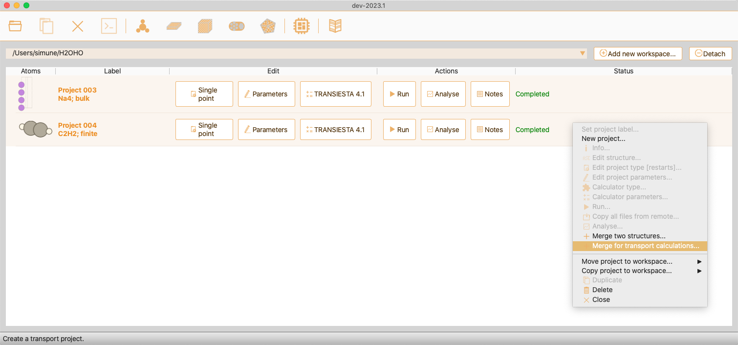
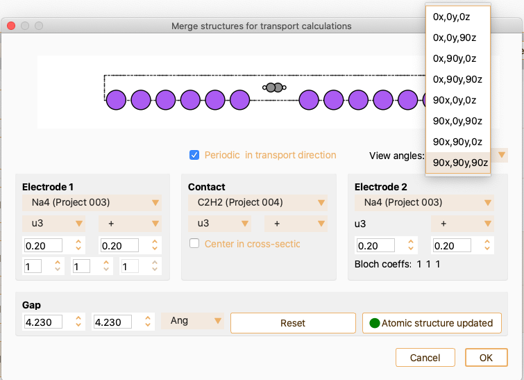
Merge for transport calculations#
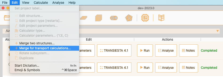
Alternatively, select the projects, right click on one of them and select Merge for transport calculations….
From the merge structures for transport calculation widget, you can tune the device structure and size. You can define the length of the contact region by tuning the Gap and the fraction of electrode cells in the contact region, see Fig. 26. Normally, it is needed to add some electrode layers in the contact region to make electrode layers out of the contact region behave as bulk.

Fig. 26 Merge structures for transport calculations widget.#
Open the dropdown menu View angles to select the desired angle for structure visualisation.
You can tune the device structure and size by modifying the parameters defining electrodes and contact. See Settings for electrode 1. to see the options offered by ASAP for tuning Electrode 1. In summary, you can:
Select the sub-system for the electrode 1 (top dropdown menu).
Select the system orientation along the transport direction. The options are the three lattice vectors (u1, u2 and u3) and the direction of the system, + or -.
Select the number of electrode unit cells in the buffer and in the contact region.
Select the k-points along the 3 lattice vectors. (bottom 3 spinboxes).
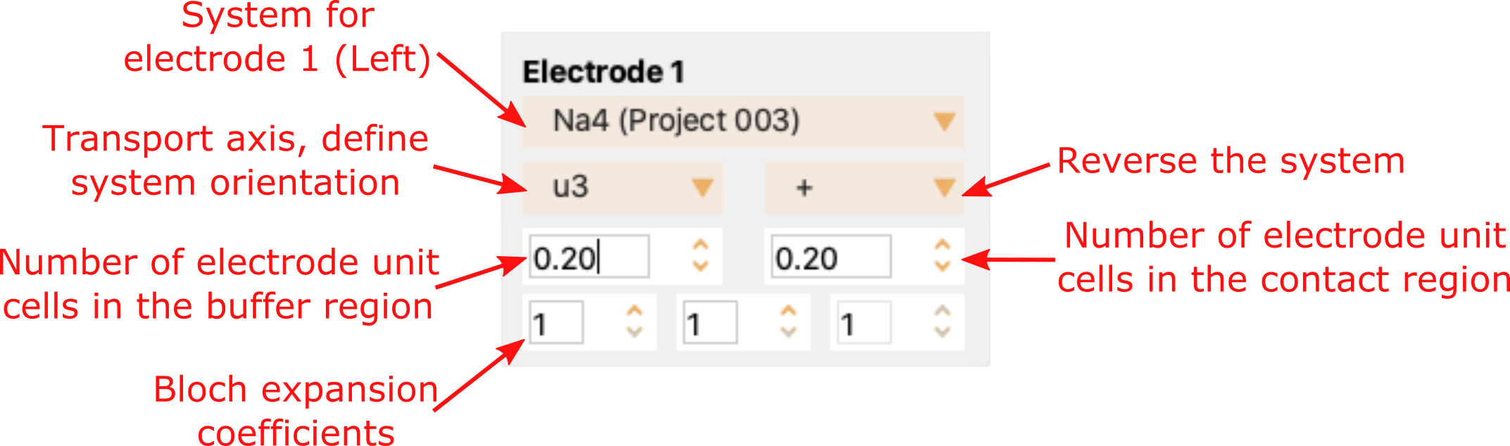
Fig. 27 Settings for electrode 1.#
The settings for the contact region and the electrode 2 have very similar tune options as Electrode 1. See Settings for contact region and electrode 2..

Fig. 28 Settings for contact region and electrode 2.#
You can use the Gap spinboxes, placed at the bottom of the widget, to change the space between the electrodes and the contact region.

