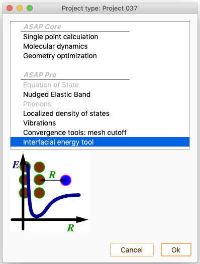
Interfacial energy tool (IET)#
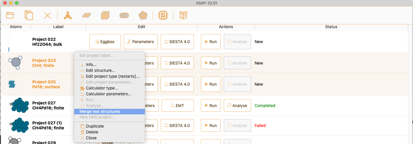
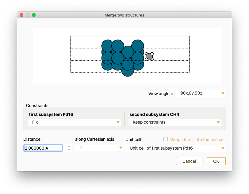
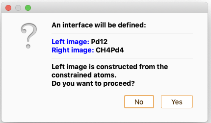
then, right-click to select the option Merge two structures to merge the two selected subsystems into one.


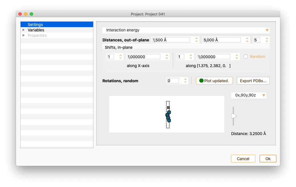
The settings widget associated with a IET type of project offers the following options:
Energy definition: The available options are
Total energy: Total energy of the system provided directly by the calculator.
Interaction energy: The interaction energy defined as
\[\Delta E = E(AB)_{ab} - E(A)_{ab} - E(B)_{ab}\]is calculated. \(E(AB)_{ab}\) is the energy of the whole system (\(AB\)) while \(E(A)_{ab}\) and \(E(B)_{ab}\) are the energy of the first and second subsystems, respectively, computed using a mixed basis set (ghost atoms).

Distances, out of plane: Minimum and maximum relative distance between the two subsystems.
Shifts, in-plane: Number of points to be sampled on the surface in the x and y directions. Check the tick-box Randomise to make a random sampling of the surface.


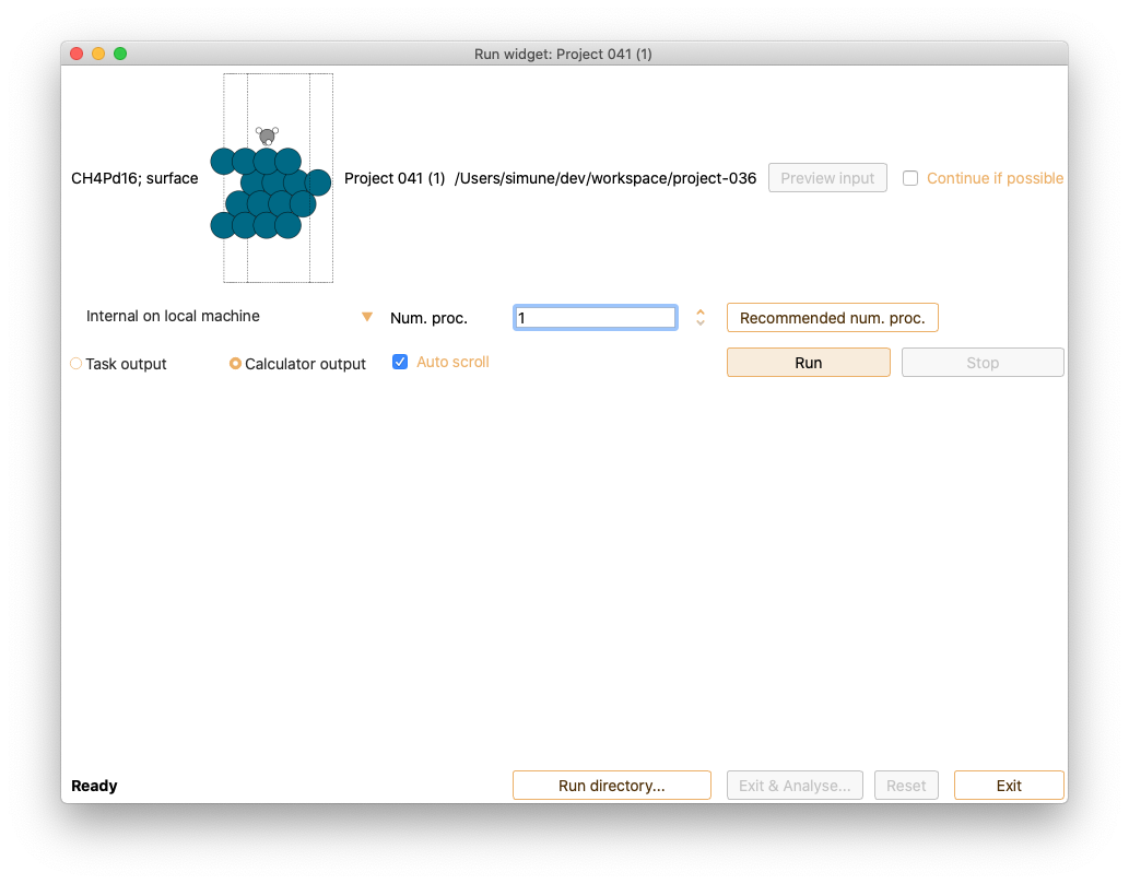
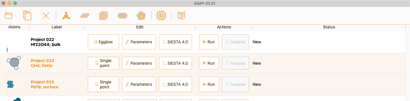
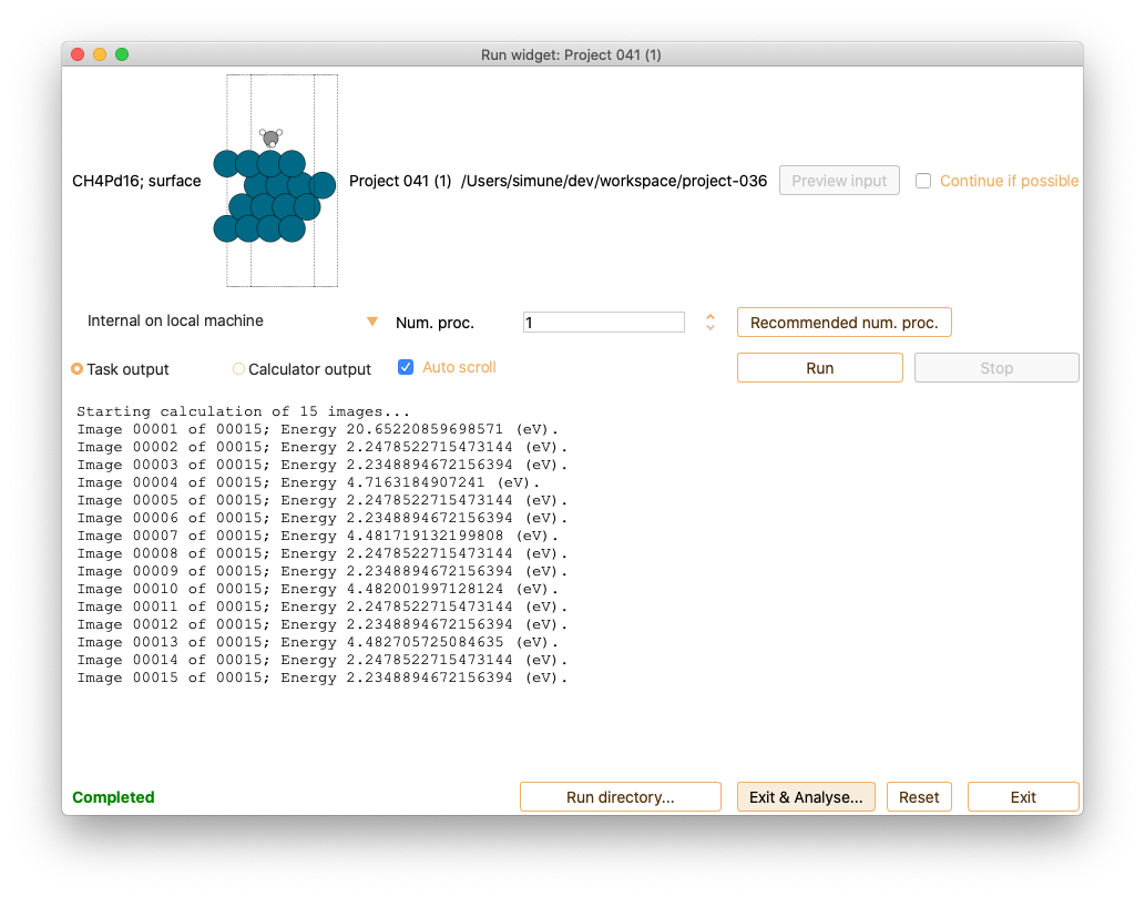
After submitting a job (run), the Calculator output tab in the Run widget shows the complete calculation output in real time.
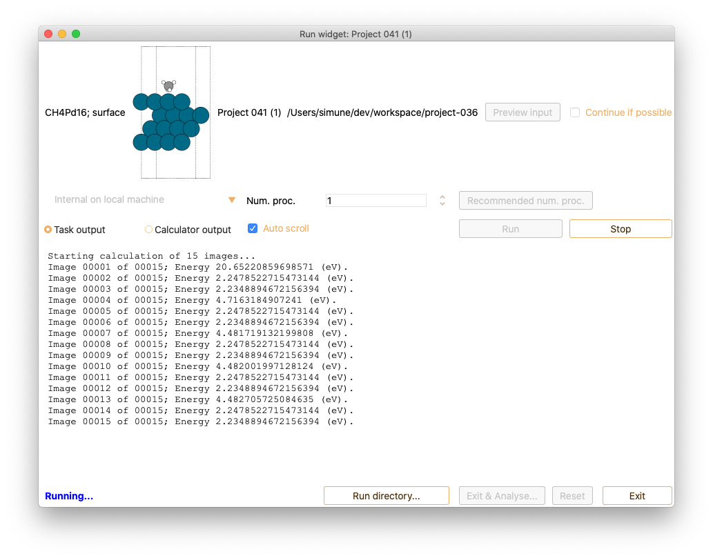
In addition, the Task output tab in the Run widget shows relevant information on the IET output in real-time. It indicates the images for which the energy has already been computed.
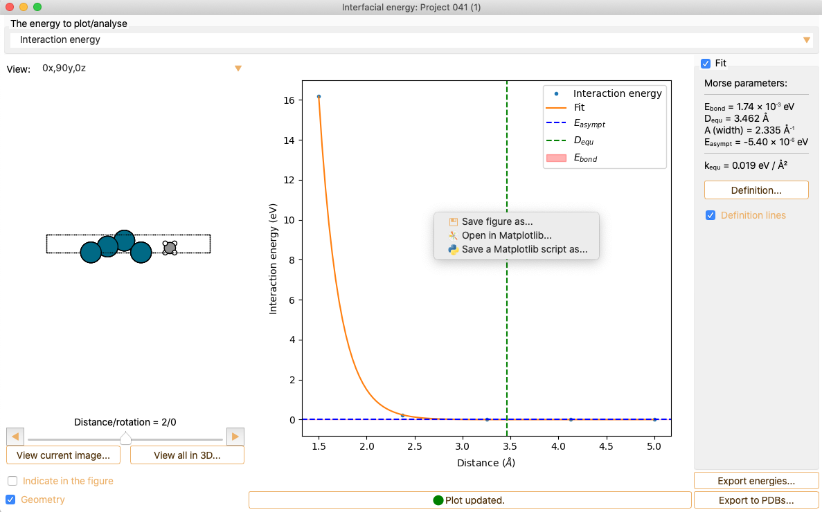
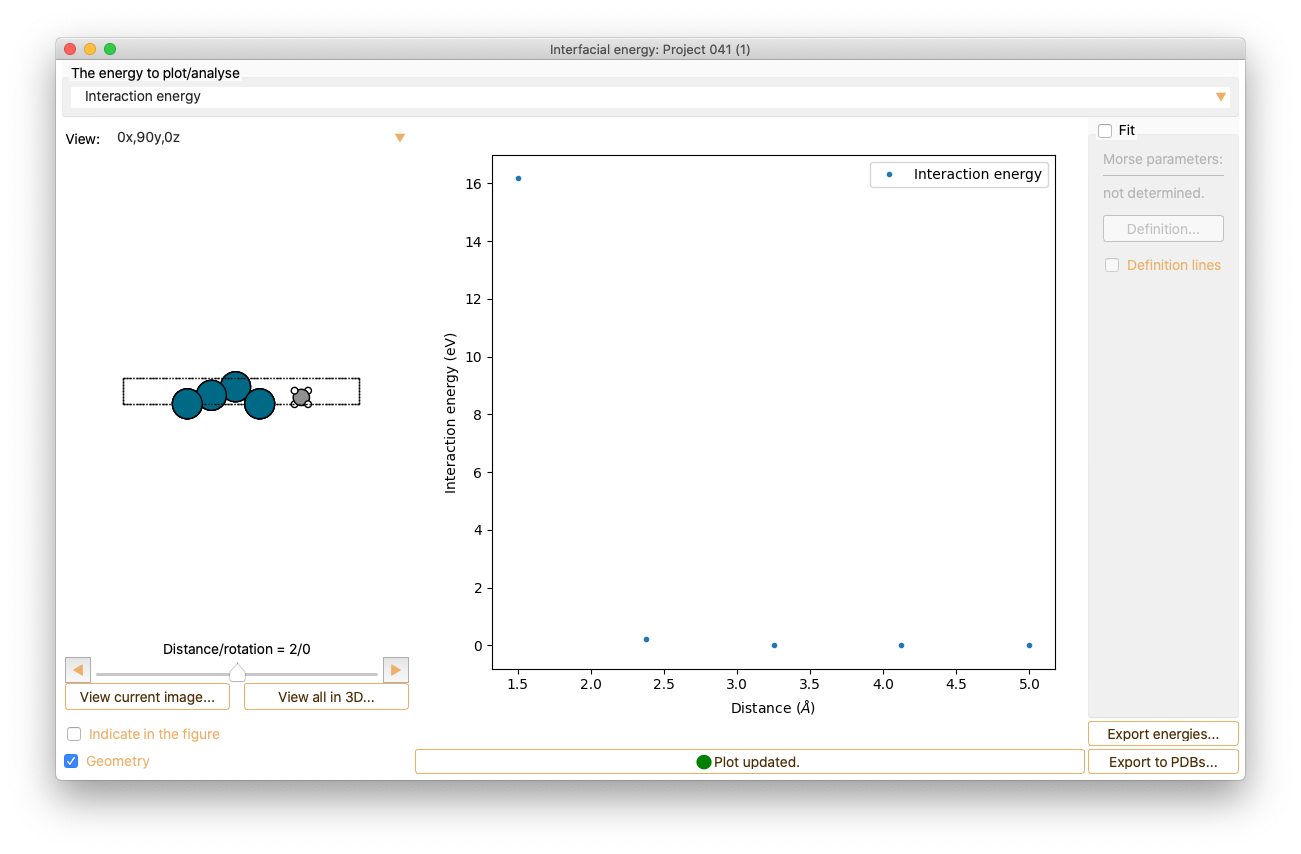
Interfacial Energy Tool workflow: Analysis#
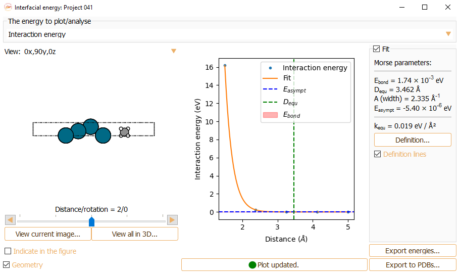
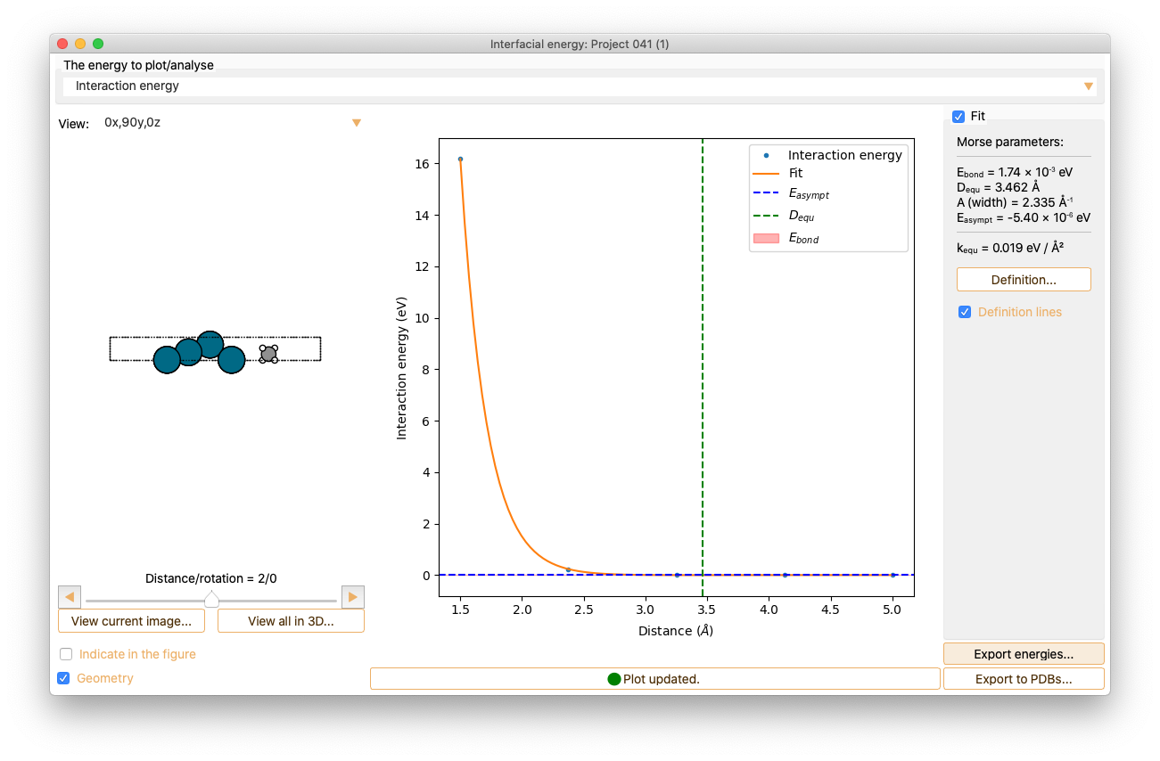
The analysis widget shows the visualisation of the energy for each of the calculated systems.
Click the Fit check box to fit the curve to the Morse potential equation and to compute the Morse parameters.
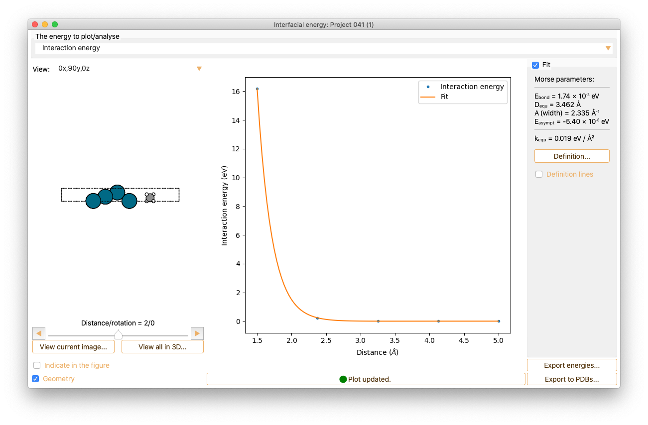
Press the Definition button to get information on the interatomic interaction Morse potential model.
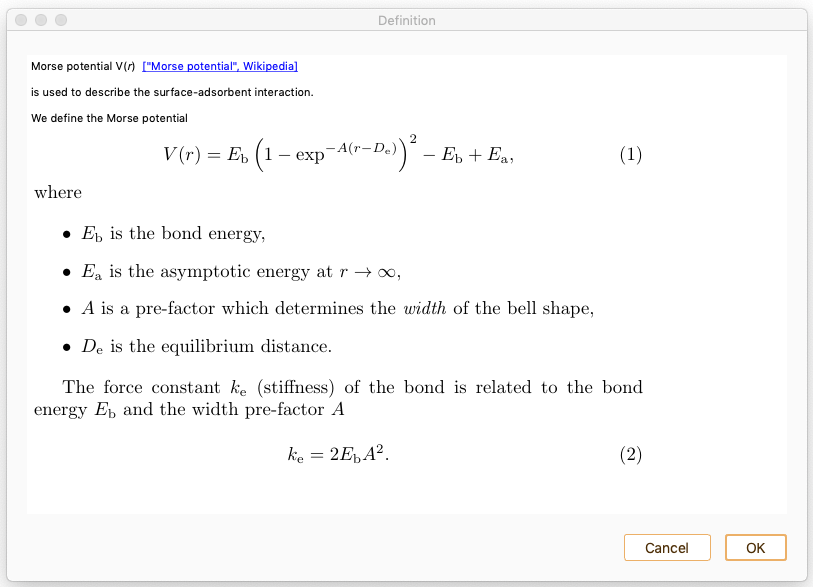
Click the Definition lines check box to visualise the relevant quantities in the figure.
Save figure as…. The supported formats are .pdf, .png, .jpg, .jpeg, .ps, eps, svg.
Open in Matplotlib…. Matplolib library allows the user an interactive visualisation of the figure (scale axis, zoom on specific X and Y values…).
Save a Matplotlib script as…. Save the Matplotlib script used to plot the figure.